
Being a junior officer and keeping a cargo watch in the CCR it carries a significant lever of responsibility.Performing well in such a specialized role requires constant learning and self-improvement. However sometimes in our efforts to develop professionally, we overlook the importance of mastering the fundamentals, such as understanding the systems we operate on daily basis. Serving on a Framo equipped vessel it is essential to be familiar with the full alarm and warning panel,for example. Despite my research, I found that comprehensive resources on the subject are limited and scattered across the web. I’ve taken the initiative to combine a little of practical experience with available online information, consolidating it into a single, accessible resource for those who wish to gain a better understanding of the topic.
Please note that the post will mostly focus on the aspects why do alarms occur and contingency measures to prevent them with brief introduction to system itself ofcourse. This is not the post to cover entire framo system in detail therefore that will hopefully be done in one of the future writings. In case you like the content please comment on the same <3 .
Therefore, lets begin.
The Framo system is a hydraulic-driven cargo handling setup used on many tankers. Instead of using electric motors in cargo tanks (which is risky in flammable atmospheres), Framo uses hydraulic oil to power submerged cargo pumps. Think of it like this, the hydraulic oil is the power carrier, pumps in each tanks are the power users and the HPU or hydraulic power-packs are the “engine” that generates this power.
The Framo alarm system is build on closed contacts meaning if anything goes wrong, real alarm or broken wire—the loop opens, the panel sees no current, it alarms.Using this kind of NC contacts for critical alarms guarantees that loss of the signal (for any reason) it raises an alarm. That is proven to be “fail to safe” in action.
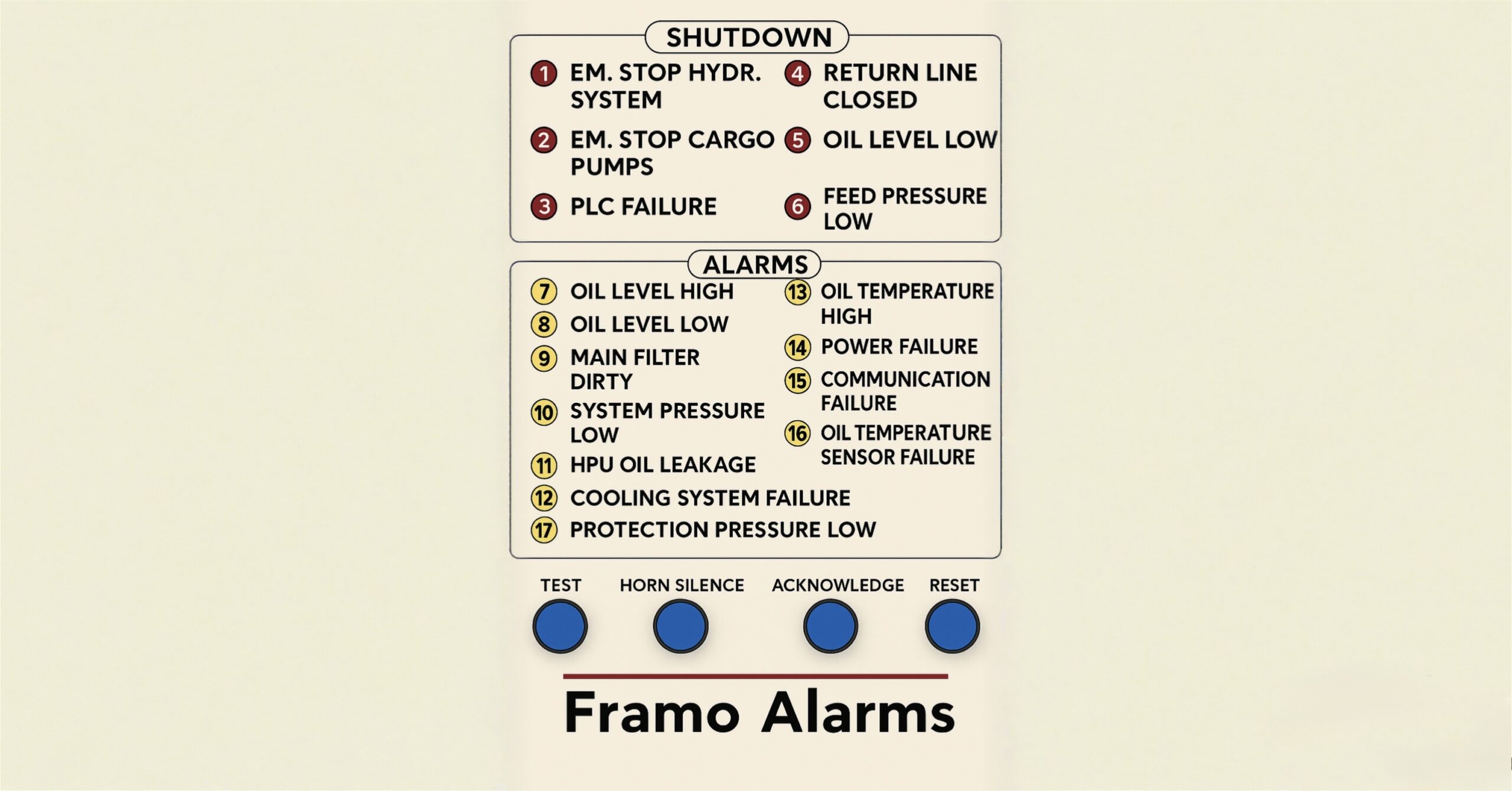
Framo classifies its alarms into two main categories:
The first category is shutdown alarms, which indicate serious faults that will stop the equipment from operating.
The second category is indication (pre-warning) alarms, which serve as early warnings to the operator and reset automatically once the condition returns to normal. When an alarm occurs, a light begins flashing and the horn sounds.
To respond, first press the Horn Silence button to stop the noise. Next, press the Acknowledge button to confirm that you have seen the alarm. If the alarm is a shutdown alarm, you must first fix the cause and then press the Reset button to clear it.
So lets start explaining each alarm in detail below …
PROTECTION PRESSURE LOW (NO.17) – The Framo system runs on a continuous circulation of hydraulic oil in a closed loop. This oil flows from the hydraulic tank to the suction side of the high-pressure pump in the hydraulic power unit (HPU) also called power-pack. On most ships, the feed pumps that supply this oil are installed on HPU 1, but in some designs they can also be found on HPU 2. There are three feed (jockey) pumps in total.When system is not fully in operation it switches to “Low Capacity Mode” meaning only one feed pump runs at a low pressure of around 3-5 bars to keep hydraulic oil moving.This constant circulation is important because it keeps the oil cool and well lubricated , prevents moisture build-up and prevents air pockets by maintaining positive system pressure. Positive pressure in the hydraulic line also means preventing vacuum conditions due to temperature variations which future lead to ingress of air and moisture, right. If you worked with the framo system you probably heard that we vent the air from the hydraulic ring line at the highest point of the system. On our ship, that point is forward, near the forecastle. The bypass valves you’ll notice there while on the catwalk, are the one on the high pressure (HP) and one on the low pressure (LP) side and while we keep both of these valves open the air bleeds out through set of venting orifices returning back to hydraulic tank.(This continuous venting mode works when Heating Mode is OFF from CCR Framo Panel). Now if the feed pump stops for any reason, the suction side of the main hydraulic pump will develop negative pressure. This immediately triggers the Protection Pressure Low Alarm. This can happen in few situations where during maintenance one feed pump is taken offline, but the other pump is not started to maintain circulation, or after a blackout or trip the system restarts but no one confirms that the feed pump is actually running. This happens because on most of the ships alarm Protection pressure low only shows in CCR and not in ECR. In this case if deck and engine team doesn’t have good coordination and if they dont follow up system can stay in this condition for hours leading to above explained issues.
HYDRAULIC OIL TEMPERATURE AND AUTOMATIC COOLING SYSTEMS (NO.12,13,16) – Every hydraulic system has an optimum oil temperature range for safe and efficient operation. Hydraulic oil should ideally be kept around 30–55 °C in a Framo cargo pump system. If the oil gets too hot, it can damage seals and other components and will age/break down the oil faster. On the other hand, if the oil is too cold, the system’s performance can suffer due to its viscosity. Thus, oil outside the optimal range requires intervention , then we can say if goes above the range it needs cooling, and if below the range it needs heating,right. Framo hydraulic units (power-packs) are equipped with an automatic cooling system to maintain oil temperature within the safe range. The hydraulic oil is routed through an oil cooler (heat exchanger) whenever cooling is needed. A temperature-sensing inlet valve to controls the flow of seawater to this cooler. (see diagram).
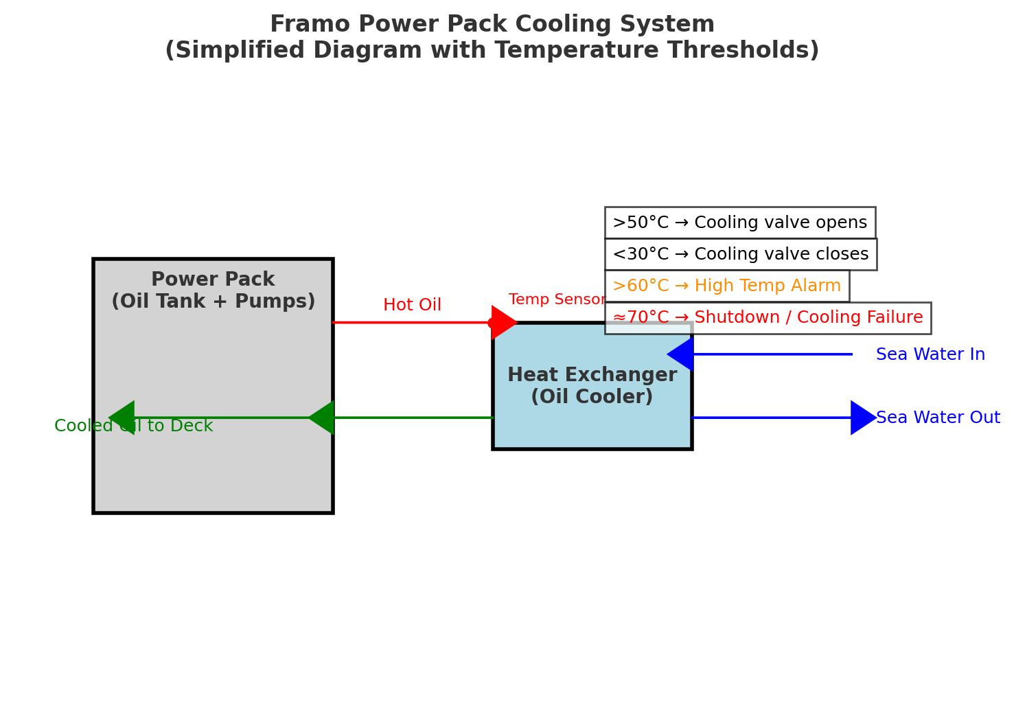
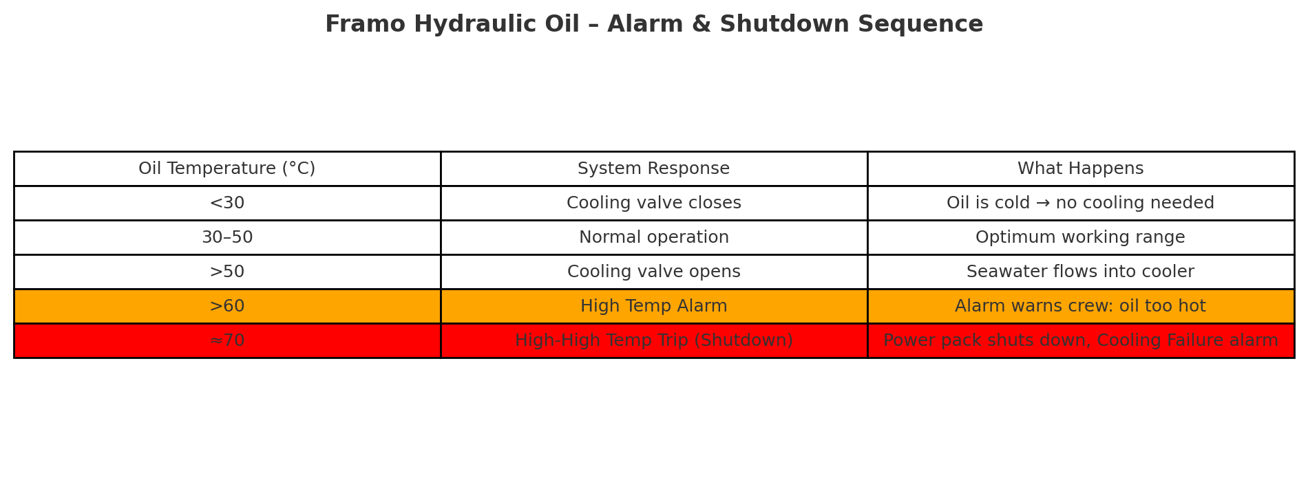
Cooling Water Inlet Valve: This valve automatically opens to send seawater through the oil cooler when the hydraulic oil temperature exceeds about 50 °C, and it closes once the oil cools down below 30 °C. In practice, this means when the oil gets hot (above 50 °C), the cooler is activated to bring the temperature down. Once cooling has brought the oil temperature under 30 °C, the valve shuts to avoid over-cooling.The Framo control system continuously monitors the hydraulic oil temperature and you will get an alert in the CCR if it gets too high. There are defined set-points for alarms and automatic shutdowns. High Oil Temperature Alarm (No.13) if the hydraulic oil temperature rises above 60 °C, an alarm will activate to warn of excessive temperature. This “high oil temperature” alarm indicates that the oil is hotter than normal operating limits and that the cooling system is likely at full capacity trying to bring it down. Crew should take action to check the cooling system (e.g.ensure the seawater supply to the cooler is flowing properly) when this alarm sounds. Duty Officer should follow up with a call to ECR to alert them of the same and make appropriate checks. Oil Temperature Trip (Power Pack Shutdown): If the oil temperature continues to climb and reaches about 70 °C, the system will automatically trip (shut down) the hydraulic power packs to protect the equipment. This is essentially an emergency cutoff to prevent damage – running the pumps with oil that hot could severely harm hydraulic components. At ~70 °C, the Framo system assumes a serious cooling system failure (No. 12) and stops the pumps.At this point alarm is telling you that the cooling arrangement couldn’t cope with the heat load, and the oil got dangerously hot. Oil Temperature Sensor Failure (No.16) – due to open circuit or broken sensor element. Control system will get no signal from the sensor which may cause alarm or even shutdown even the oil temperature is normal. Over time sensor can drift away from real values meaning showing incorrect reading and to physical damage (corrosion, sea water leakage, vibration and etc.). Please note below Alarm and Shutdown sequence table.
I have also noticed that many junior officers and engineers are still not fully aware of the exact operation of the venting and heating valves located at the foremost part of the ship. Therefore, let us briefly explain their function and operation…
Framo hydraulic oil lines (HP & LP) form a closed loop (ring line) running all around the deck. Just like in any piping system, the best way to remove air bubbles is to vent from the highest point, because air naturally migrates upwards.On an MR tanker with a Framo system,the highest elevation of the deck ring line is at the forward catwalk area near the forecastle. At this point, you will see two vertical standpipes — one from the HP line and one from the LP line. At the base of each standpipe, a ball valve is fitted. These valves allow you to isolate either the HP or LP side from the Heating & Venting block whenever required. The two standpipes then join into a bypass line that leads to the Heating & Venting block. Please see diagram below with detailed information for operating the valves
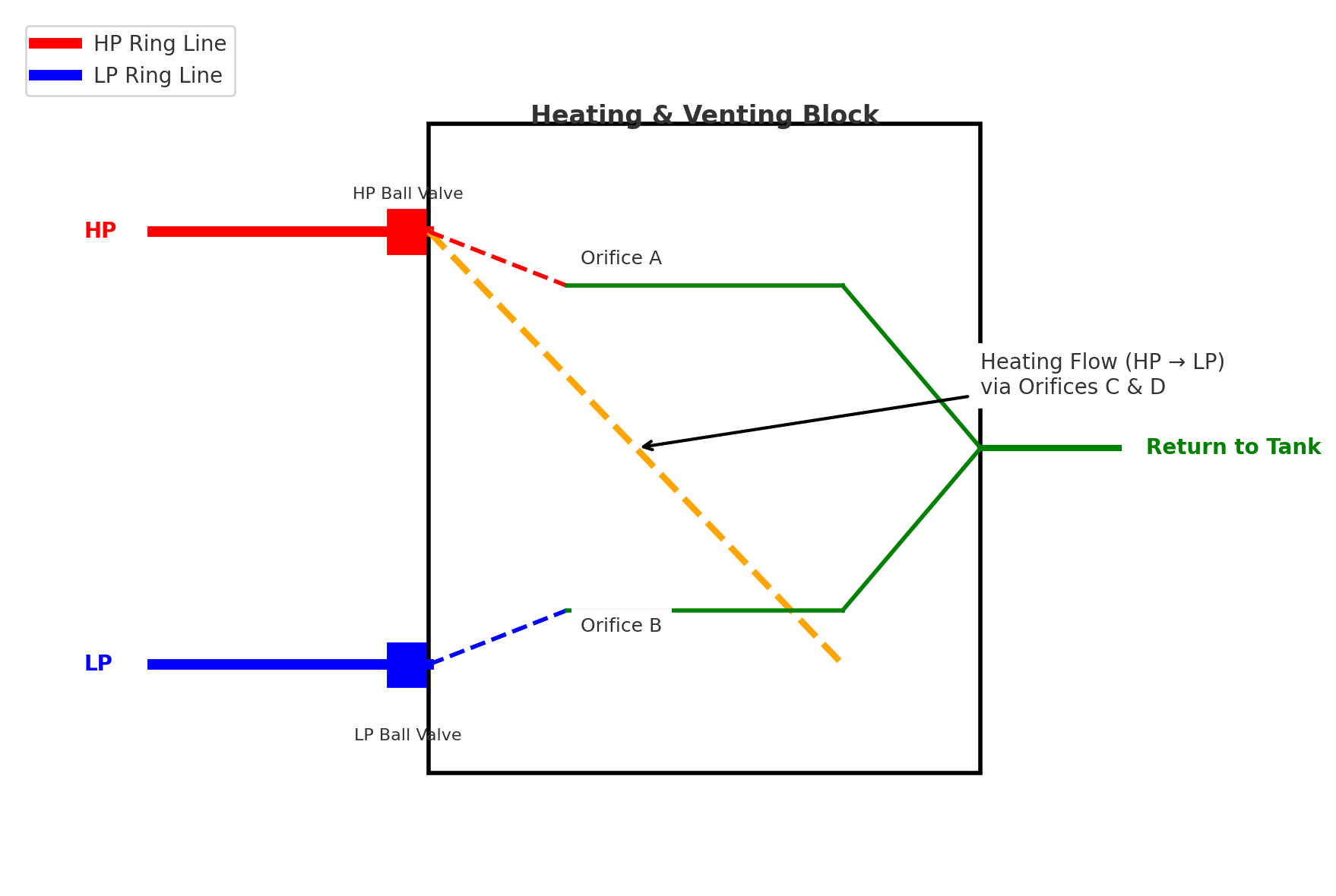
By keeping both HP and LP ball valves open, a small bleed flow continuously removes any air trapped in the ring LP and HP hydraulic lines.This bleed flow passes through Orifice A (from HP) and Orifice B (from LP) and join the green pilot line which takes the oil back to the hydraulic tank.The amount is very small (<3 L/min), but just enough to keep the system air-free all the time.If oil needs to be warmed (for example in cold weather), you press the Heater ON button on the Framo panel in the CCR and start HPU (powerpack) at around 100 bars.This energizes the pilot line, which shifts the internal spool inside the Heating & Venting block.Once shifted, the block connects HP and LP lines together through Orifice C &D. (orange dotted line). A controlled HP → LP flow is now created, which causes circulation and frictional warming of oil in the ring lines. In simple words: The same block that bleeds the air also doubles up as a “heater bypass,” using set of dedicated orifices which gently warm the system oil when you need it. So to simplify this small Heating & Venting block forward on the catwalk is actually doing two big jobs quietly in the background – bleeding air 24/7 and warming oil on demand.
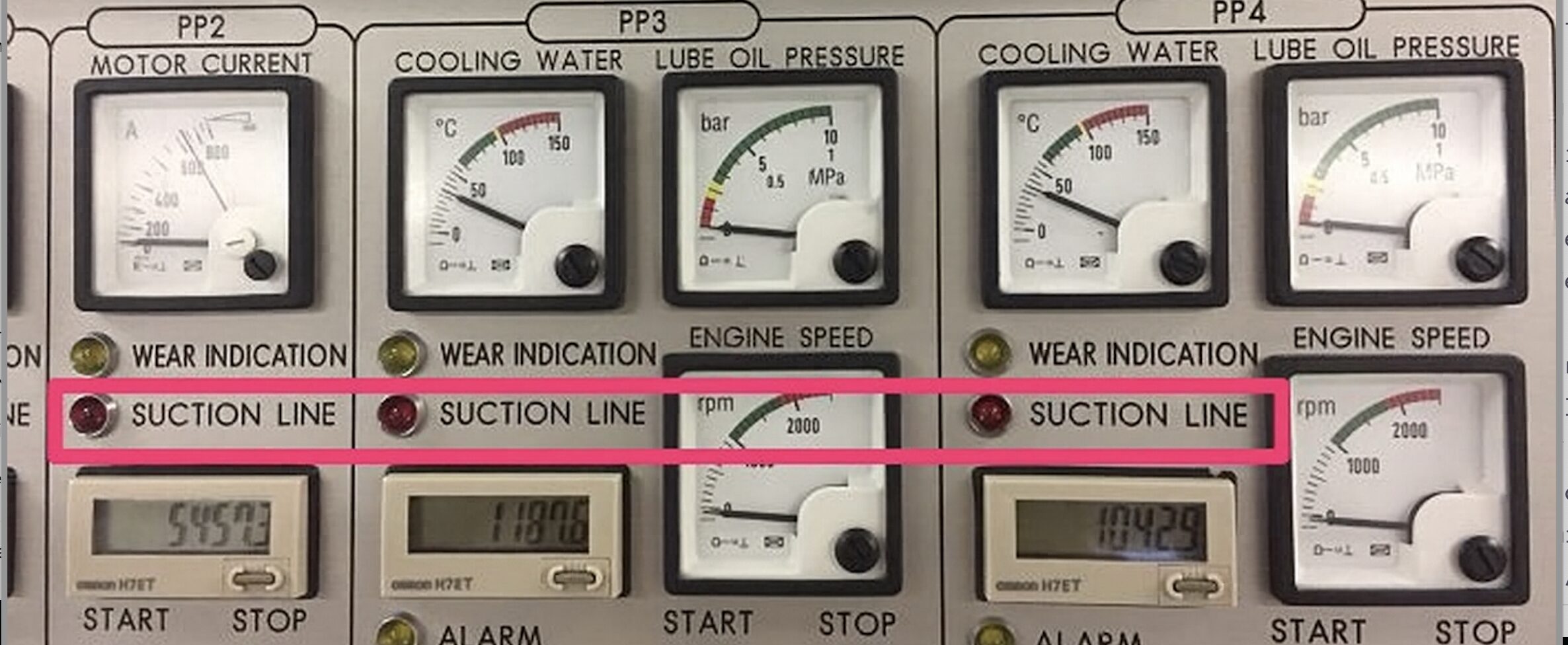
SUCTION LINE TRIP – Framo cargo pump systems are equipped with safety interlocks to protect the hydraulic power unit (HPU) / power-pack and pumps from damage. One critical safeguard is the suction line valve trip alarm – a shutdown alarm that activates if the suction valve to the HPU’s high pressure pump is not fully open. Suction valve must be always fully open to enable supply of oil from hydraulic oil tank to the HPU pump inlet. The suction line trip uses a sensor on the suction valve to detect its position. The sensor confirms whenever the suction valve is fully open before allowing the HPU to run. If the valve is not fully open, the sensor signal (or lack of the same) cases immediate trip to the HPU’s electric motor and triggers the audible/visual alarm. It’s a simple but vital feature to prevent pump cavitation,overheating and damage. In the earlier systems, the suction valve on the HPU was typically a manual valve (often a butterfly or gate valve) with a lever or handle. A mechanical limit switch was installed such that the valve’s handle would physically press against the switch when the valve was fully open. Essentially, the valve handle touching the sensor confirmed an ”open” condition. If the suction valve was even slightly closed, the handle would lose contact with the sensor, causing the circuit to open and immediately activate the trip alarm. New Framo Systems have improved Proximity sensors with no Physical contact needed. The Suction valve in newer system is often an actuated or self-indicating valve and a proximity sensor is mounted to detect the valve’s position electronically. The proximity sensor (for example, inductive or magnetic sensor) is aligned with a target on the valve spindle or actuator. When the valve is fully open, the target is sensed – sending an ”okay” signal to the control system. If the valve is not fully open, the sensor does not detect the target , and the system register that as a ”valve closed” condition,. In effect it serves the same purpose as the old mechanical switch but is less prone to mechanical wear or misalignment. The alarm is latched , meaning it will stay on until the condition is corrected and the alarm is acknowledged/reset.
In a hydraulic system, the power pack, which supplies pressure to the system, must always have enough oil to work properly, because without sufficient oil it can lose suction and stop functioning. To prevent this from happening, the system is equipped with a low oil level warnings and trip’s, which can automatically shuts down the power pack when the oil level falls below the minimum mark, thereby protecting the system from damage.During normal operation, the oil level in the hydraulic tank is kept just above the low-level alarm point, so that if there is any leakage in the hydraulic lines, the alarm will be triggered quickly and give an early warning before too much oil is lost. This setup ensures that the system remains protected from damage due to low oil, that any leakage is detected at an early stage, and that excessive loss of hydraulic oil is avoided.
At the same time, it is also important to make sure that the oil level does not become too high, because an overfilled tank can cause foaming, overflow, and increased pressure inside the system, which may lead to operational problems or damage.
OIL LEVER HIGH (7) – A high oil level alarm means that the oil inside the hydraulic tank has gone above the normal operating range, usually when the tank is more than 90% full. This alarm does not cause an automatic shutdown, but it is still very important and should never be ignored. There are several reasons why the oil level might become too high. Sometimes it happens because the tank was accidentally overfilled during maintenance. Another common cause is water leaking into the hydraulic oil tank through a faulty cooler. For example, if a cooling coil bursts, seawater can enter the tank, and since water is heavier than oil, it will collect at the bottom while pushing the oil level higher. Cargo can also enter the hydraulic system through a damaged cargo pump shaft seal, which increases the total fluid volume in the tank and raises the oil level. If the high level is caused by water or cargo contamination, then the quality of the oil is no longer good, and this can seriously damage hydraulic system components over time. It is also possible for the oil level to rise temporarily due to thermal expansion if the oil is heated too much without proper venting, or because of air entrainment, where air bubbles expand once the system is stopped, pushing the oil level up. In rare cases, the alarm might even be caused by a faulty or miscalibrated sensor. Even though there is no automatic shutdown for a high oil level, the alarm should be treated seriously. The duty officer should immediately contact the Engine Control Room (ECR) so that the further checks can be carried out. If the tank becomes too full, it can overflow into the HPU room, creating a mess and possible safety hazards. For this reason, high oil level alarms are an important warning sign that must always be followed up quickly.
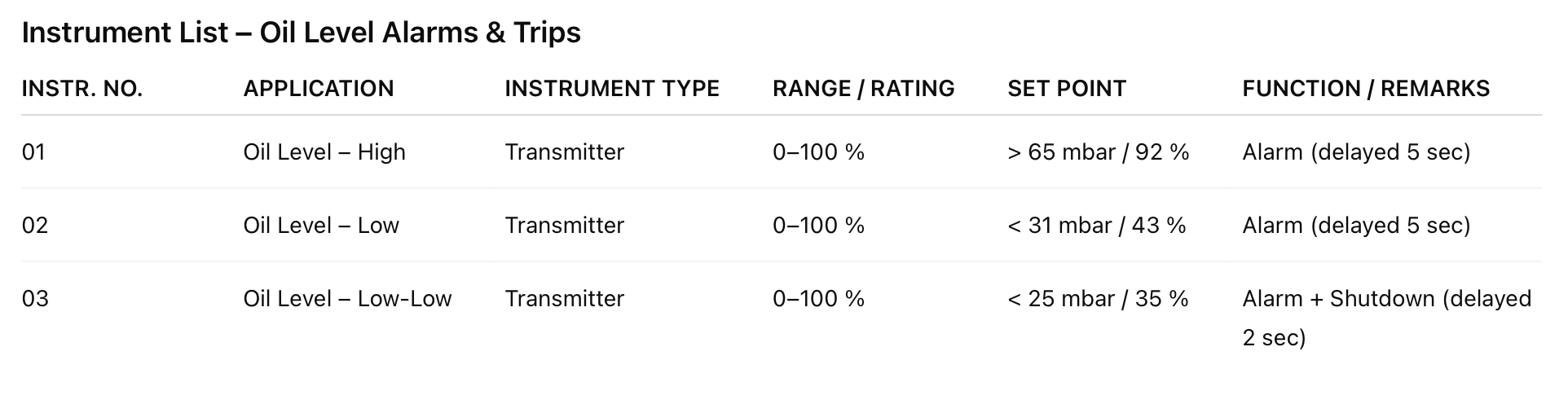
OIL LEVER LOW (No.8) & LOW LOW (No.5) – The ”Oil Level Low” alarm comes when the hydraulic oil in the HPU tank falls below the set low level, which is usually around 40% of the tank capacity (see diagram above), but not yet low enough to trigger the Low-Low shutdown. This alarm is normally an indication of a minor leak or gradual oil consumption over time. The most common causes are small leaks at pipe fittings, valve seals, or pump seals that slowly weep oil and reduce the level. These leaks are not always immediately visible but will add up and cause the alarm after some days. Another reason could be recent maintenance where oil was drained for work but not fully refilled, in which case the alarm will appear once the pumps start and fill up the lines. Sometimes air trapped in the system can also make the level appear lower, because when pumps run, oil replaces the air in the lines and the tank level drops, although this should stabilize once the air is vented out. The Framo system is designed so that the normal level is kept just above the alarm point, which means even a slight loss of oil will trigger the alarm early. Although a faulty sensor can rarely be the cause, the oil level low warning should always be assumed real until it is verified otherwise.When this alarm comes, the crew will see a flashing light and hear a buzzer in the CCR. At this stage there is no automatic shutdown, and the HPU and pumps continue to run. However, the alarm is a critical early warning because if the level continues to drop, it will soon reach the Low-Low set point <35 % oil lever , which will trip the system.
Note: The system’s low-level trips are there to save the pumps; never bypass them except in a dire emergency and under controlled conditions.
If the situation is not addressed quickly, a number of secondary problems can occur. A low oil level can allow air to enter the hydraulic circuit before the Low-Low protection activates, which will cause erratic pressure, cavitation noises, and spongy motor performance. Air inside the oil also increases oxidation and reduces cooling efficiency, while the reduced oil volume means there is less reserve for cooling and the temperature can rise. The initial cause of the low level may also become worse, because a small leak can easily grow under system pressure and lead to a larger rupture, a big spill, and eventually a Low-Low trip that stops all operations
EMERGENCY STOP HYDRAULIC SYSTEM (No.1) & CARGO PUMPS (No.2) – According to class requirements, the Framo system is equipped with several emergency stop (E-Stop) arrangements to ensure safe cargo operations.On deck, emergency stop push buttons are located on both sides of the manifolds. These buttons are designed to stop the cargo pumps only. All other hydraulic consumers, including the ballast pumps, remain unaffected when these stops are used.In contrast, the emergency stop button on the hydraulic system control panel in the CCR, as well as the one located at the central position outside the engine room, will stop the entire hydraulic system. This includes the cargo pumps and all other hydraulic consumers such as ballast pumps.When a total system shutdown is initiated, the PLC issues stop commands to the power packs in a controlled sequence. The first power pack stops immediately, and each subsequent power pack receives its shutdown command with a 0.75 second delay, preventing hydraulic shocks in the system.If a bow thruster motor and control system is installed, the E-Stop push buttons on the thruster panels will stop the bow thruster only, without affecting other hydraulic consumers.In practice, cargo pump emergency stops are tested regularly, usually during pre-arrival port checks. This is crucial to ensure the system can be stopped quickly from all available locations during cargo operations. The HPU power packs normally remain running unloaded, with system pressure dropping back to idle even when the pumps are stopped. If an E-Stop is activated, cargo flow ceases abruptly and almost instantaneously, preventing any further pumping.A complete emergency stop of the entire hydraulic system is usually tested once a month or quarterly, depending on company requirements, and always in coordination with the engine room. Because a full E-Stop places significant stress on the system — with abrupt stops creating pressure spikes and mechanical stress — its use is reserved for true emergencies and scheduled testing only, as per company guidelines.
PLC FAILURE (No. 3) – The Framo cargo pumping system is controlled by a Programmable Logic Controller (PLC) installed inside the control panel. This PLC is programmed by Framo and provides all the logic needed for the safe and automated operation of the hydraulic power units (HPUs) and cargo pumps. For example, system pressure is normally set from the CCR control panel using a potentiometer. This provides a voltage input to the PLC, which then regulates pressure through proportional control valves.If the PLC fails, the control logic for the HPUs and cargo pumps is lost. Since Framo systems are designed to be fail-safe, any PLC fault will trigger an automatic shutdown of hydraulic power to prevent uncontrolled pumping. As a result, both the HPUs and cargo pumps will stop, bringing cargo operations to an immediate standstill until control is restored.This can be especially problematic if a PLC failure occurs during active pumping. Cargo may remain standing in the lines — for example, heavy cargoes like EUW winter grades or palm oil — which can solidify or cause delays in restarting operations.In the event of a PLC failure, the first step is to inspect the PLC unit and its power supplies. Often, a tripped breaker or a blown power supply module may be the root cause.Framo systems also include a manual override mode located at the back of the CCR control panel. In Mode 2, activated via a key switch, operators can bypass the PLC and allow limited pump operation using hardware switches. However, this should only be used under strict guidance and with great caution.When operating in override, the crew must manually monitor all critical parameters such as oil level, system pressure, and temperature, since many automated safety protections are bypassed. At the same time, it is essential to coordinate with Framo service engineers for troubleshooting or replacement of the PLC hardware as soon as possible.
POWER SUPPLY (No. 14) – When we talk about power failure in hydraulic system control panels, the first thing to know is that these panels are normally connected to two different power sources — one is the main feeder and the other is the back-up feeder — so that if the main feeder fails for any reason, the system will automatically switch over to the back-up without us having to do anything. To make troubleshooting easier and to make sure that a single problem does not bring down the whole system, the control system is further divided into smaller sub-systems, and each one of these sub-systems has its own dedicated 24V DC power supply, which means that even if one sub-system has an issue, the others can keep running without being affected. Both the feeders and the DC power supplies are continuously monitored by relays, and these relays are connected to status lamps, so whenever the feeder or the supply is healthy, the corresponding lamp will remain lit, giving us a quick visual confirmation that things are fine. If there is a failure in any of the feeders, or in any of the DC supplies, or if there is a short circuit, then the system will immediately generate what is called a “potential free” or “dry contact” alarm signal, which is sent both to the engine control room and also appears at the control panel itself, ensuring that we are aware of the power failure right away.
The content published on this blog reflects my personal opinions and understanding, and does not represent the views of any organization or employer. All information is provided “as is,” without any express or implied warranties of accuracy, completeness, or fitness for a particular purpose. I accept no responsibility or liability for any errors, omissions, or outcomes resulting from the use of this information. Readers are solely responsible for how they apply the material, and should exercise proper judgment, professional standards, and, where appropriate, consult qualified experts before acting on any of the content. By using this blog, you understand that the content is for informational purposes and is there to complement your judgment only.
Leave a Reply